Chapter 6: Tera Calculation 3_Logistics Equipment Space Calculation
Section 1: PL_Ass Calculation
Overview of Automated Pallet Warehouse (PL_Ass) Calculation
This function is a simulation tool for calculating the storage capacity of an automated pallet warehouse, the corresponding installation area, and the "virtual floor" area related to legal regulations.
1. Calculation of Storage Capacity and Installation Area
- Calculation of Storage Capacity: The storage capacity per warehouse unit is calculated by "Number of Rows × Number of Bays × Number of Tiers".
- Automatic Calculation: By inputting the number of units, bays, and tiers, the total storage capacity and required installation area are automatically derived.
- Reflecting Settings: By changing the rack specifications (Tera Settings) and pressing the "Calculate Start (Re)" button, the area based on the latest design values is immediately updated.
Calculation Logic for Firewalls and "Virtual Floors"
In connection with Japanese legal regulations, area calculations employ the concept of a "virtual floor" depending on the height of the automated warehouse. This significantly impacts the firewall installation standards (required every 1,500$m^2$).
Criteria for Adding Virtual Floors
Depending on the height of the racks (top surface of the highest cantilever), the virtual floor area is added as follows.
| Height of the Highest Tier | Treatment of Virtual Floor |
|---|---|
| Less than 5m | No virtual floor |
| 5m to less than 10m | Virtual floor = Rack installation area (excluding cargo handling aisles and inspection paths) |
| 10m to less than 15m | Virtual floor = Rack installation area × 2 |
Determination of Firewall Installation
- Judgment Criteria: It is determined that a firewall is necessary every time the sum of the "Actual Installed Floor Area + Virtual Floor Area" exceeds 1,500$m^2$.
- Through this simulation, you can examine in advance how increasing the "height" of the warehouse will affect fire prevention costs (the number of firewalls).
Benefits of Introduction and Utilization
- Confirmation of Legal Compliance: Because the required number of firewalls can be grasped during the planning stage, it is useful for accurate estimation of construction costs.
- Optimization of Spatial Efficiency: The optimal rack configuration (number of bays and tiers) can be derived considering the balance between storage efficiency and legal regulations.
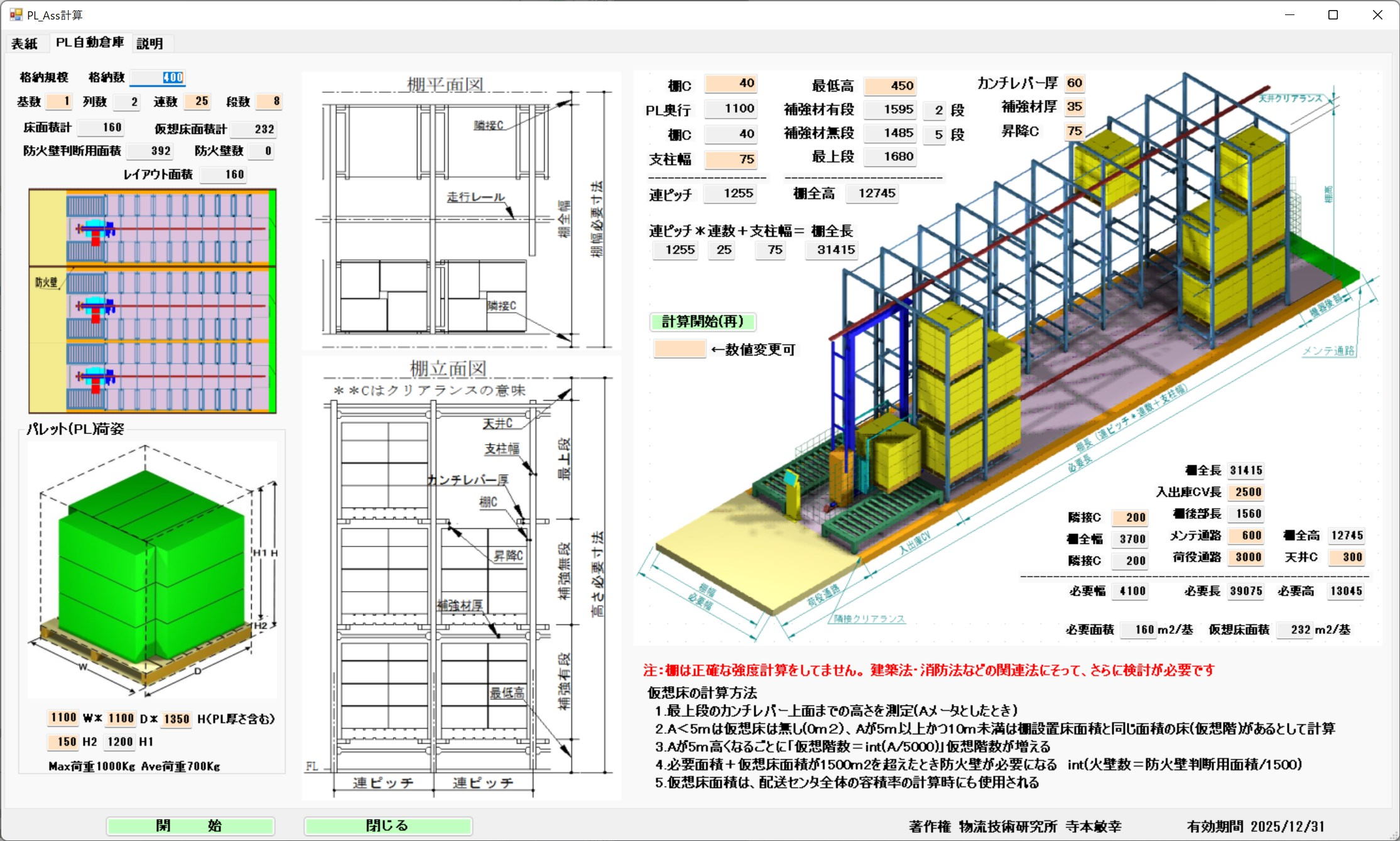
Calculation Method and Firewalls (Virtual Floors)
The storage capacity of 1 unit is Number of Rows * Number of Bays * Number of Tiers.
In the figure to the left, the storage capacity is calculated by the number of units, bays, and tiers, and the installation area is calculated automatically.
By changing the Tera Settings for rack specifications and pressing the "Calculate Start (Re)" button, the installation area is calculated reflecting those changes.
Firewalls are installed every 1500m2, but virtual floors are added for every 5m increment.
As an example:
If the top surface of the highest cantilever is less than 5m, there is no virtual floor.
If the top surface of the highest cantilever is 5m to less than 10m, Virtual floor = Rack installation area (excluding cargo handling aisles and inspection paths).
If the top surface of the highest cantilever is 10m to less than 15m, Virtual floor = Rack installation area * 2.
A firewall is required for every 1500m2 of Installed Floor + Virtual Floor.
Section 3: Electric Racks
Overview of Electric Racks (Mobile Racks)
Electric racks consist of fixed pallet racks mounted on electric carriages. By moving the carriages sideways, the system can share cargo handling aisles. This allows for a significant reduction in aisle space compared to fixed racks, increasing storage efficiency.
Structural Characteristics
- Height Variation: Because electric carriages are used, the overall rack height is taller than normal fixed racks by the height of the carriage (approx. 250mm).
- Reuse of Fixed Pallet Racks: The specifications of the racks themselves mounted on the carriages follow the standards for fixed pallet racks explained in Section 2.
Space Design and Clearance
Area calculations for electric racks reflect maintenance spaces and aisle concepts specific to the equipment.
- Reflecting PL Dimensions: When pallet dimensions are changed, the required area for the entire electric rack is interactively recalculated.
- Adjacent Clearance: Because a control panel is installed on the back of the rack, an adjacent clearance (separation distance) of 400mm must be secured.
- Necessity of Auxiliary Aisles: If the rack area is close to main aisles, separate auxiliary aisles may not be necessary.
Simulation Example of Area Efficiency
Based on the calculation example in the document (4 Rows × 5 Bays × 4 Tiers × 2 PL = 160 PL), the changes in occupied area per 1 pallet (PL) are as follows.
| Condition | Installation Area | Area per 1 PL |
|---|---|---|
| When including auxiliary aisles | — | 0.79 $m^2$/PL |
| When excluding auxiliary aisles | 107 $m^2$ | 0.67 $m^2$/PL |
As shown, since the storage efficiency per pallet varies greatly depending on the aisle design, optimization through simulation is important.
Calculation Screen
For electric racks, fixed PL racks are mounted on electric carriages and moved to share cargo handling aisles.
The rack becomes taller by the 250mm height of the carriage. For the fixed PL racks mounted on the carriages, refer to the fixed PL racks in Section 2.
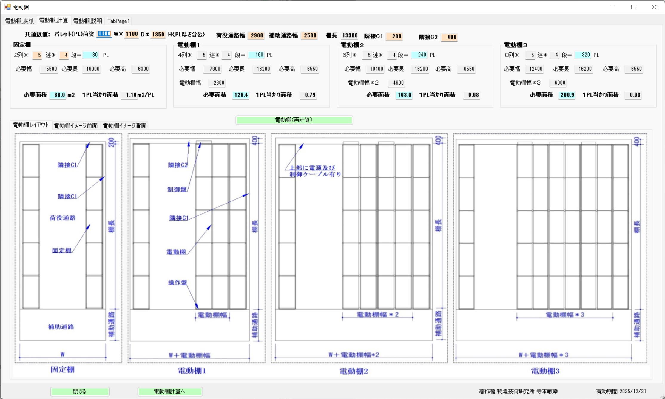
PL Dimensions and Adjacent Clearance
The electric rack area is recalculated reflecting the change in PL dimensions.
Auxiliary aisles are not required if they are close to the rack area. A control panel is on the back of the rack, requiring 400mm of adjacent clearance.
Required Area and Area per PL
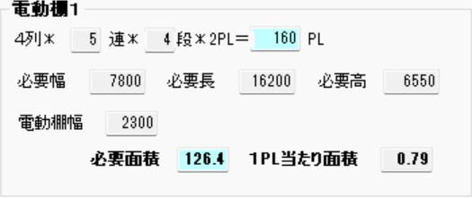
4 Rows * 5 Bays * 4 Tiers * 2 PL = 160 PL
For Electric Rack 1, the area per 1 PL is calculated as 0.79m2/PL including the auxiliary aisle area.
However, if the auxiliary aisle area is excluded, the installation area becomes 107m2, resulting in 0.67m2/PL.
Section 4: Automated Bucket Warehouse
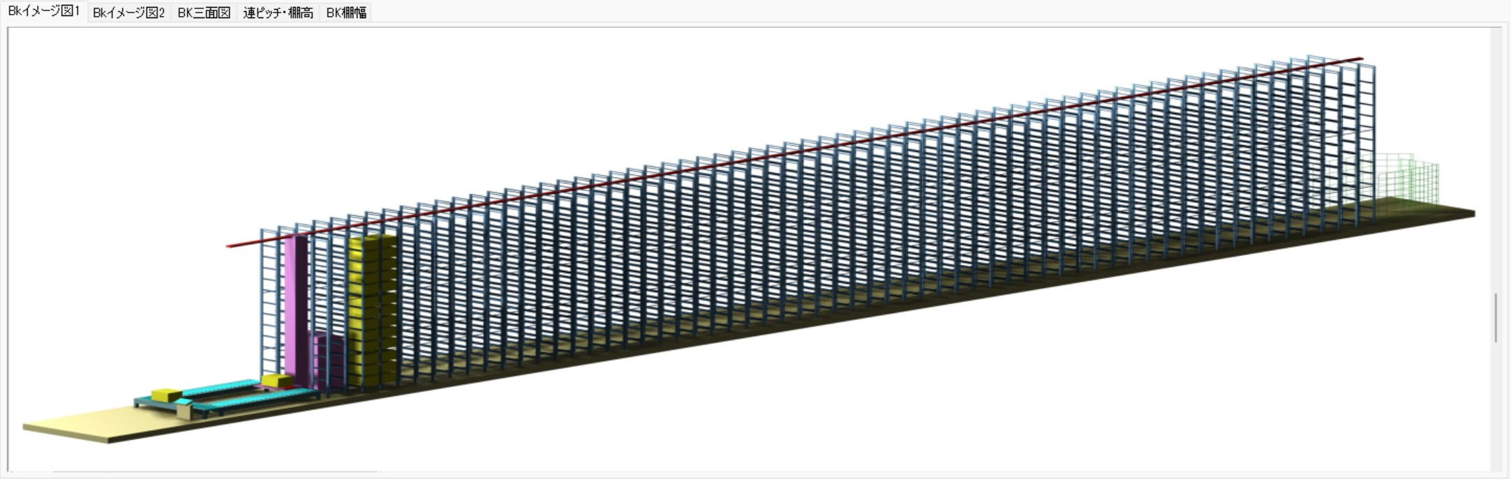
Basic Structure of Automated Bucket Warehouse
An automated bucket warehouse is a system that performs multi-tier, high-density storage using dedicated container boxes (buckets).
- Basic Configuration: Two rows of racks are arranged per unit, and a transport crane (stacker crane) travels between them to handle cargo.
- Cantilever Type Racks:
- Containers are stored straddling boards (cantilevers) extending from the rack pillars.
- The crane's slide plate scoops up the bottom of the container to perform loading and unloading.
- Restrictions on Storage Containers: Only dedicated containers of predetermined dimensions can be stored. Items with different dimensions or weak cardboard boxes cannot be stored directly.
⚙️ Operations and Picking Formats
Incoming and outgoing conveyors are installed at the front of the racks, where the following operations are performed.
- Retrieval Method: There is a method to retrieve the entire container as is, and "piece picking" where only the required quantity is taken out.
- Piece Picking: After picking products from a retrieved container, the container with the remaining products is automatically stored again.
- Work Environment: Cargo handling aisles and conveyor spaces are required for workers to move efficiently.
Design Dimensions and Clearance
By changing the Tera Calculation settings, automatic calculations based on the latest designs are possible.
Example of Dimension Calculation
A standard calculation example when using a Type 51 container (width 550mm) is as follows.
| Item | Dimension Setting Example |
|---|---|
| Rack Width (Total) | 1,910mm (Rack Depth 555mm × 2 Rows + Crane Width 800mm) |
| Building Adjacent Clearance | 200mm (Margin between the building wall and the rack) |
| Inter-Unit Clearance | 150mm (Spacing when arranging 2 cranes in parallel) |
Rack Components
Racks are not uniform; they consist of classifications such as "First Tier," "Highest Tier," "Reinforced Tier," and "Normal Tier" depending on their structural roles, and these are also reflected in the calculations.
Calculation Screen
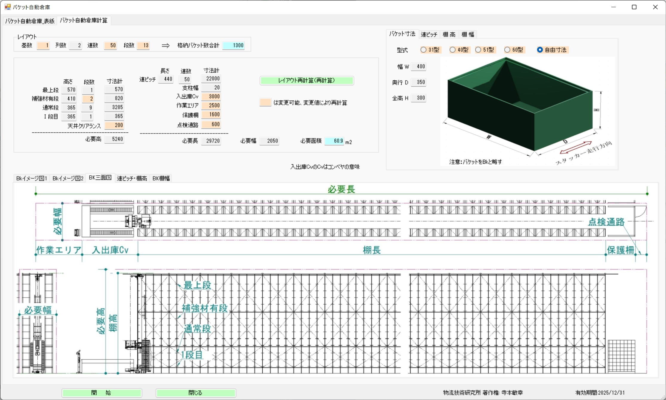
Photo Heading

Per unit:
A transport crane travels between 2 rows of racks.
The rack is a cantilever type
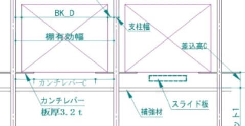
Boards (cantilevers) extend from both rack pillars, and container boxes are stored straddling these boards.
The slide plate from the traveling crane cargo handling device is inserted into the rack, scoops up the bottom of the container box, and pulls it from the rack onto the traveling crane.
Container boxes of predetermined dimensions are used; containers with different dimensions cannot be stored, and even if the dimensions are the same, weak cardboard cannot be stored.
Incoming and outgoing conveyors are installed at the front of the racks, where workers perform storage and retrieval operations. Cargo handling aisles are also necessary.
There are container unit retrievals and piece picking.
In piece picking, products are picked from the retrieved container, and the container is re-stored.
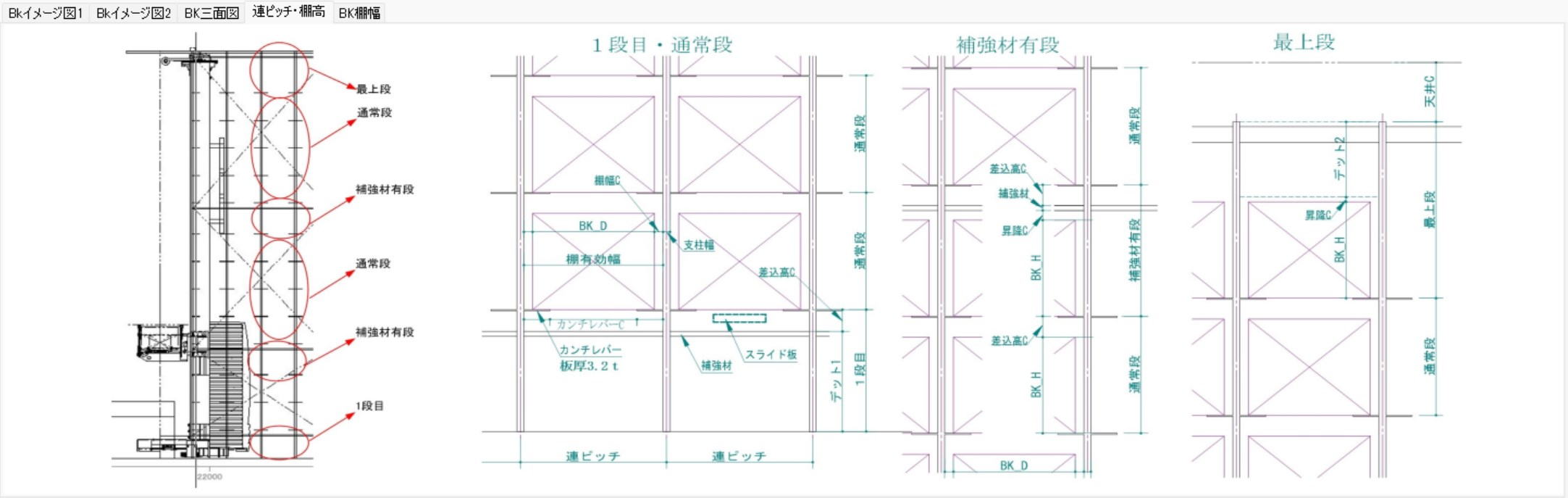
The rack structure
is divided into the first tier, the highest tier, reinforced tiers, and normal tiers.
By changing the Tera Setting numerical values,
calculations are performed automatically reflecting those changes.
The rack width is
For a Type 51 container (550mm)
Rack Depth 555mm * 2 rows + Crane Width 800mm, totaling 1910mm.
The building adjacent clearance is 200mm.
The inter-unit clearance when there are 2 cranes is 150mm.
Section 5: Automated Case Warehouse Calculation
Overview and Features of Automated Case Warehouse (SAS)
The automated case warehouse (SAS: Shuttle Automated Storage) is highly reliable logistics equipment with a track record of over 700 installations since its introduction in 1985. Recently, as patent restrictions have expired, many logistics manufacturers have begun selling it, drawing renewed attention.
1. Advanced Sorting and Sequencing Functions
- Individual Management Capability: Capable of managing 1,000 items individually when storing 1,000 cases.
- Sequenced Retrieval: Equipped with a powerful sorting function that allows retrieval by specifying a "shipping sequence" according to the destination.
2. Overwhelming Storage and Retrieval Capacity
Because high-speed traveling carriages (shuttles) move independently on each tier of the racks, it demonstrates capacity surpassing conventional systems.
- Capacity per Carriage: Capable of 50 to 70 storage/retrieval operations per hour.
- Overall System Capacity: For example, in a 15-tier configuration, it has a capacity of 60 operations × 15 tiers = 900 operations per hour.
3. Dramatic Improvement in Work Efficiency (Picking Comparison)
Compared to manual labor, picking speed accelerates significantly at the SAS retrieval station.
- Flow Racks (Manual): Picking efficiency of about 1 pick every 12 seconds (300 picks/hr).
- SAS Retrieval Station: High-speed picking of 1 pick every 5 seconds (720 picks/hr) is possible.
Efficiency for Low-Liquidity Destinations/Items
The SAS solves at once the challenges of the "low-liquidity" (infrequently shipped) areas, which are the most difficult to mechanize and the most labor-intensive in a distribution center.
Continuous Mixed Work of Cases and Pieces
- Elimination of Load Consolidation: Its greatest feature is the ability to continuously perform case unit shipping and piece unit shipping.
- Specific Example: When there is an order for "1 case" and a "total of 15 pieces across 3 items" for a low-liquidity destination, these can be mixed and worked continuously, making load consolidation work entirely unnecessary in later processes.
Design Dimensions and Practical Considerations
Tera Calculation enables highly accurate simulations reflecting the following numerical values.
- Storage Capacity: Accommodates cases with length, width, and height ranging from 150mm to 600mm, capable of storing approximately 2,000 cases in 1 unit (2 Rows × 15 Bays × 13 Tiers).
- Maintainability: Designed with inspection walkways installed every 2,000mm in height, allowing for manual retrieval even when stopped due to trouble.
- Structural Arrangements: Because the traveling carriage overhangs below the rails, care must be taken regarding dimensional interference depending on the presence of walkways.
- Legal Regulations (Virtual Floors): If the highest tier exceeds 5m, the area is added as a "virtual floor" based on regulations.
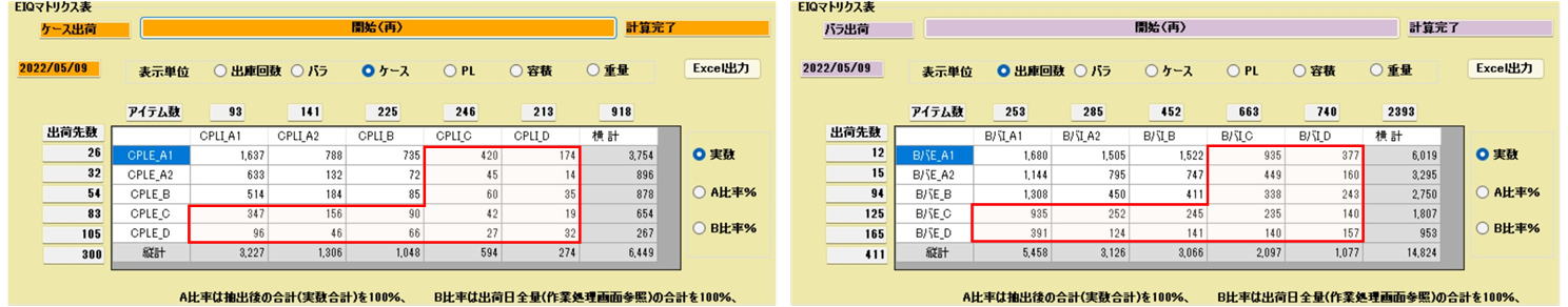
Below, low-liquidity destinations and low-liquidity items in the red frame are placed in the automated case warehouse, and shipped mixed by destination.
Calculation Screen
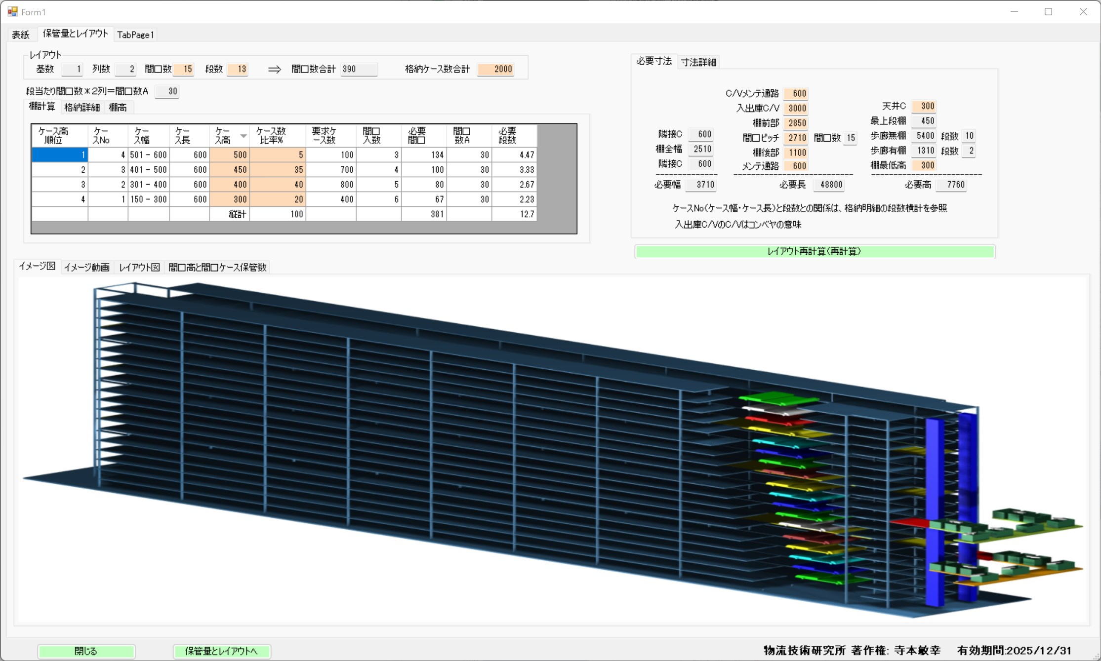
Case Packaging and Storage Capacity
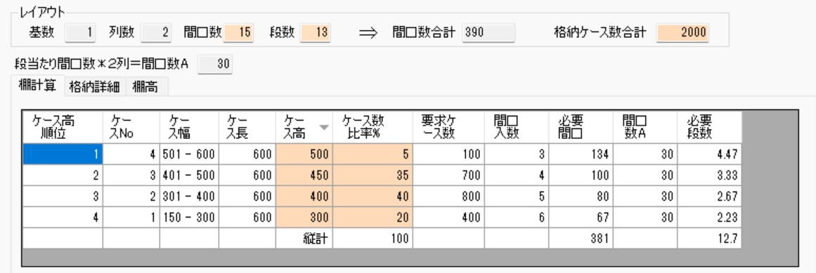
The calculation of the number of stored cases is based on fixed conditions because any case with a length, width, and height between 150-600 can be stored.
Under the conditions in the table to the left, the storage capacity of 1 unit (2 Rows * 15 Bays * 13 Tiers) is 2,000 cases.
Please change the Tera Settings in the left table to verify the changes in storage capacity.
Operation of Automated Case Warehouse

Incoming cases are transferred from the internal conveyor,
transported to the rack slot, and stored in the rack.
Moves to the rack slot containing the case to be retrieved, transfers the case,
transports and unloads the case onto the internal rack conveyor,
and transfers it to the external retrieval conveyor via a vertical conveyor.
The above storage and retrieval can be performed 50-60 times per hour.
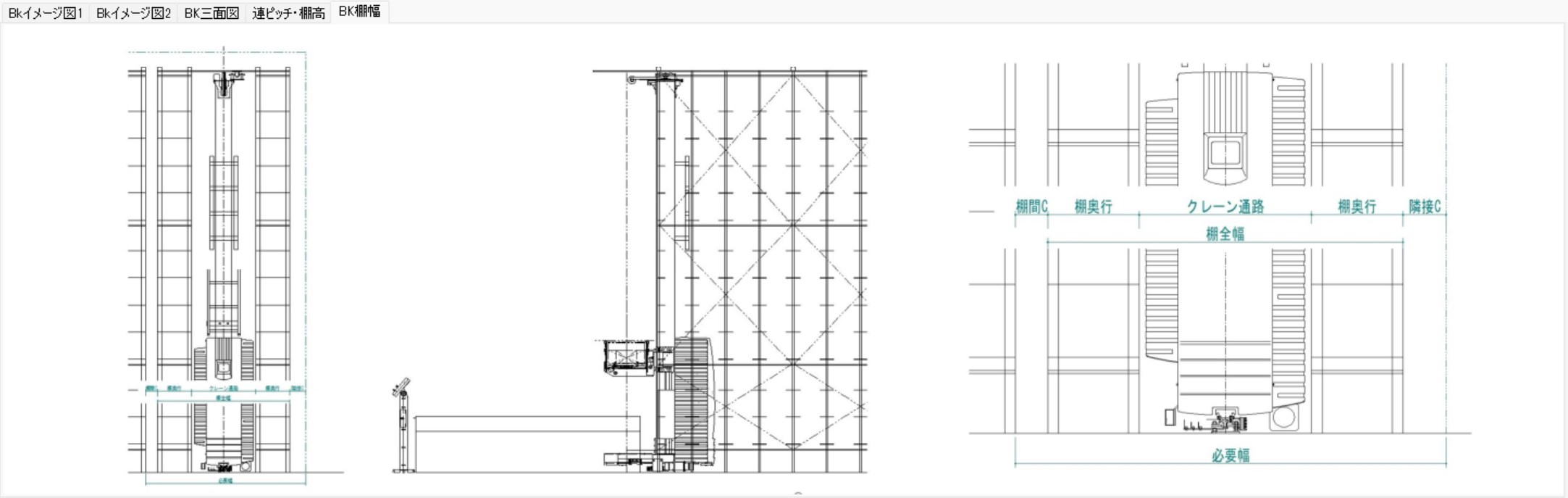
Planar Layout
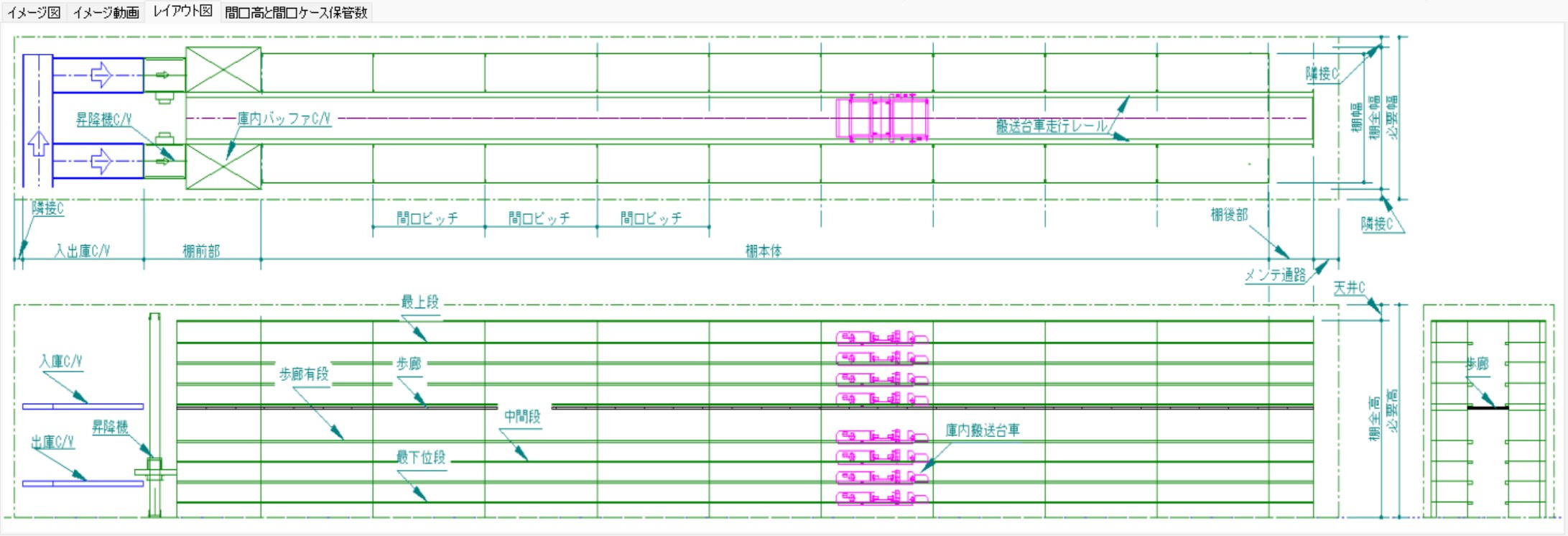
Incoming and outgoing conveyors can be installed at the front and back of the case racks. (The layout above is front only.)
Walkways are installed at 2000mm height intervals, making retrieval possible during trouble stoppages.
Calculated assuming a virtual floor exists for every 5m exceeded by the highest tier.
Traveling Carriages, Rack Slot Height/Width, and Number of Stored Cases
Slot pitch 2710mm, number of stored cases per slot:
6 cases for a 300mm wide case, 5 cases for a 400mm wide case, 4 cases for a 500mm wide case, 3 cases for a 600mm wide case.
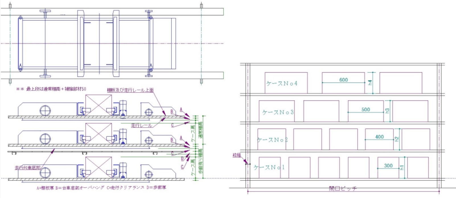
Photo Heading
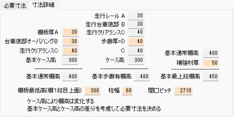
The traveling carriage structure overhangs below the rails, so pay attention to the dimensional arrangements between slots with walkways and those without.
Tera Settings can be modified.
Section 6: Flow Rack Calculation
Basic Structure and Calculation of Flow Racks
Flow racks are structured so that cargo received from the back flows forward (to the retrieval side) due to an incline; these racks are suited for First-In, First-Out (FIFO).
- Calculation of Number of Racks: The total number of racks is calculated by "Number of Rows × Number of Bays".
- Unit Configuration: Flow racks are composed of independent "Single Racks" and "Add-on Racks" installed sharing pillars with adjacent racks.
- Characteristics of Fill Rate: Because cases of various dimensions are temporarily stored in a fixed rack width, the rack's fill rate generally tends to be low.
⚙️ Picking Efficiency and Operational Considerations
In designing flow racks, it is important to consider the attributes of the workers (such as height) and picking frequency.
- Operation of the Highest Tier:
- Because it is difficult to retrieve cargo from the highly positioned top tier, it is suitable for storing products with low retrieval frequency.
- In workplaces where female workers are the majority, consideration is needed, such as providing step stools or setting the height of the top tier lower.
- Storage Efficiency vs. Work Efficiency:
- Reducing the number of tiers (e.g., from 4 tiers to 3 tiers) decreases storage capacity by 25%, but workability improves correspondingly. Careful judgment through simulation is required to determine whether to prioritize storage volume or picking efficiency.
Design Dimensions (Clearance)
- Building Adjacent Clearance: The distance between the building (walls, etc.) and the rack is typically set to 100mm.
- Automatic Calculation: By changing the numerical settings in Tera Calculation, the required area reflecting these operational conditions is instantly calculated.
Calculation Screen
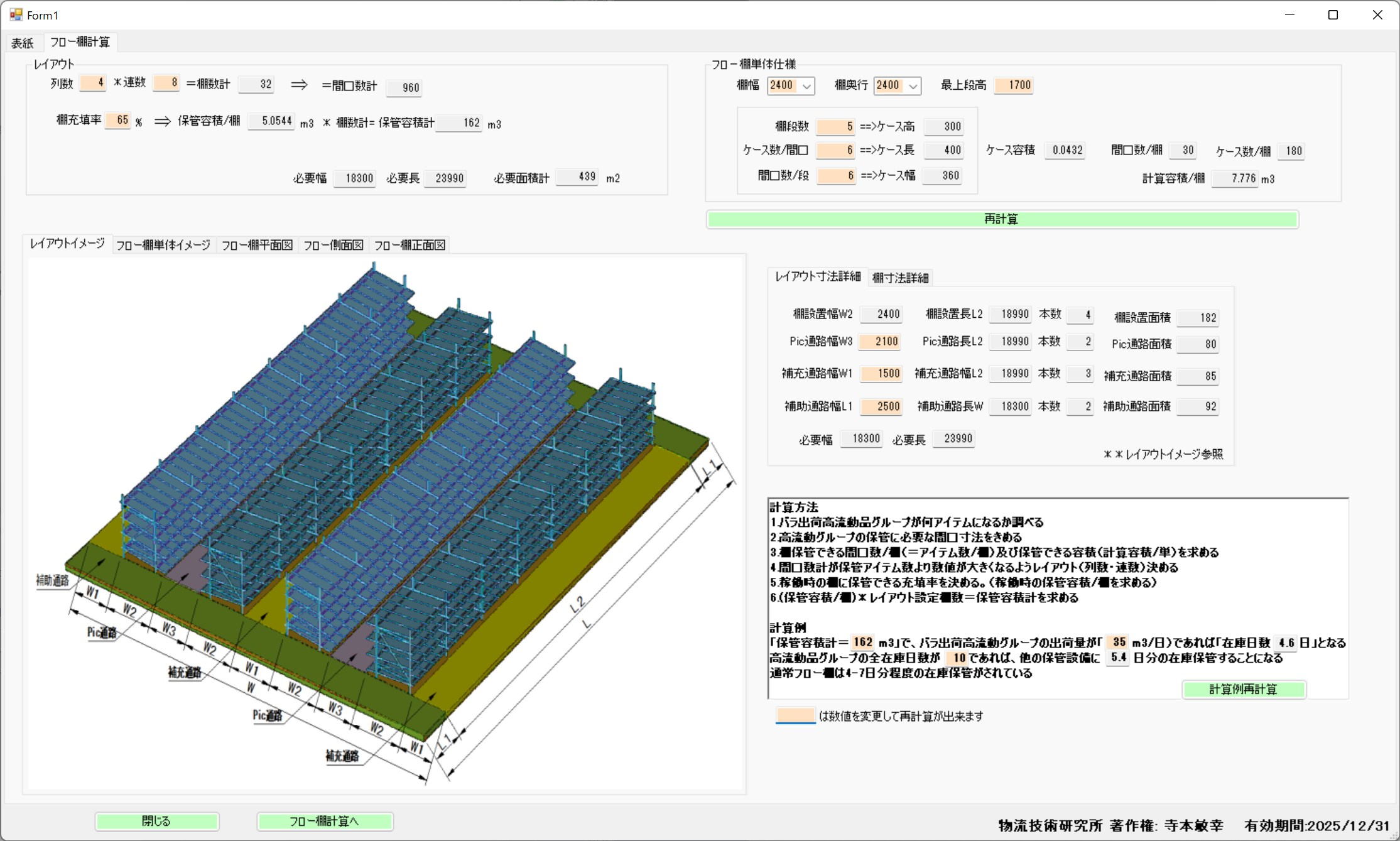
Photo Heading
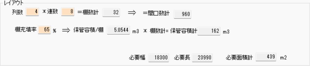
Number of Racks = Number of Rows * Number of Bays
Flow racks consist of single racks and add-on racks
(Add-on racks share pillars with adjacent racks).
Since cases of various dimensions are temporarily stored in a fixed rack width, the rack fill rate is inferred to be very poor.
Photo Heading
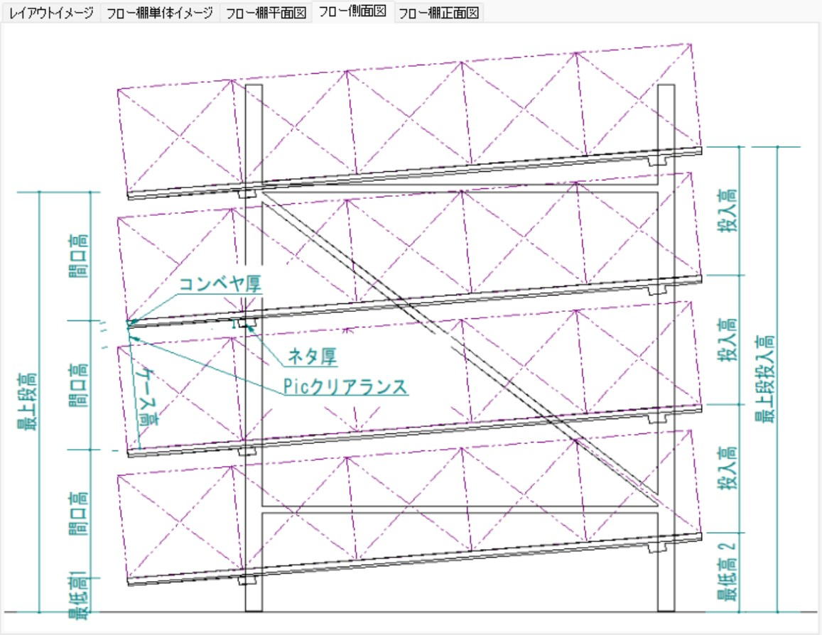
Because the top tier is difficult to reach, it stores products with infrequent retrieval.
Usually, women do the picking, so it is necessary to either provide a step stool or
lower the top tier to suit women.
Changing a 4-tier rack to 3 tiers results in a 25% decrease, making it a difficult choice between prioritizing picking efficiency or storage.
Adjacent clearance to the building is 100mm.
Section 7: Medium-Duty Rack Calculation
Basic Specifications and Area Calculation for Medium-Duty Racks
The installation area for medium-duty racks is automatically calculated by setting the rack's specific dimensional specifications (width, depth, height) along with the number of rows and bays to be placed.
- Selectable Size Settings:
- Rack Width: 1,800 / 2,100 / 2,400 mm
- Rack Depth: 300 / 450 / 600 / 900 mm
- Rack Height: 1,800 / 2,100 / 2,400 mm
- Number of Tiers: 3 / 4 / 5 / 6 Tiers
- Rack Slots: 2 / 3 / 4 / 5 / 6 / 7 / 8 Slots (Number of item divisions per tier)
- Adjacent Clearance: While large equipment exceeding 3,000mm in height (automated warehouses or fixed pallet racks) require a 200mm gap, medium-duty racks or flow racks under 3,000mm in height can be designed with a 100mm adjacent clearance.
⚙️ Rack Fill Rate and Item Management
To maximize the storage capacity of medium-duty racks, flexible slot design corresponding to item size is important.
- Optimization of Slots: The number of items stored on one tier does not need to be fixed. By combining small-volume items with large-volume items, dead space on the rack is reduced and the fill rate is improved.
- Dispersion of Storage Areas: Items targeted for storage are managed by dispersing them into two locations: the "Inventory Storage Area (Reserve)" and the "Shipping Operation Area (Medium-Duty Racks)."
Simulation of Inventory Days and Replenishment Cycles
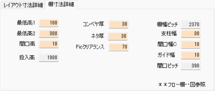
In Tera Calculation, inventory days on medium-duty racks can be calculated based on inventory volume estimation calculations.
Calculation Example
When simulating under the following conditions, the inventory days that can be held on medium-duty racks is 14 days' worth.
- Inventory days for the entire center: 40 days
- Effective storage volume of medium-duty racks (after factoring in 70% fill rate): 35 $m^3$
- Inventory volume of the entire center: 100 $m^3$
- Calculation Formula: $(35 m^3 / 100 m^3) \times 40 \text{Days} = 14 \text{Days}$
Practical Point: Considering the workload of replenishing from the inventory area to the medium-duty racks (operation area), it is ideal to design the operation area to hold 20 days or more worth of inventory.
Estimation of Item Composition (Calculation Based on Empirical Values)
Estimates the dispersion status of items between the inventory area and the operation area according to shipping frequency (Rank B, C, D items).
- Number of Items in Operation Area (Medium-Duty Racks): 1,000 items
- Number of Items Reduced in Inventory Storage Area: 210 items
- Calculation Example: $(14 \text{Days (Medium-duty rack inventory)} / 20 \text{Days (Ideal inventory)}) \times 1,000 \text{Items} \times 0.6 = 210$
- Result: The inventory storage area will be composed of 790 items.
Calculation Screen
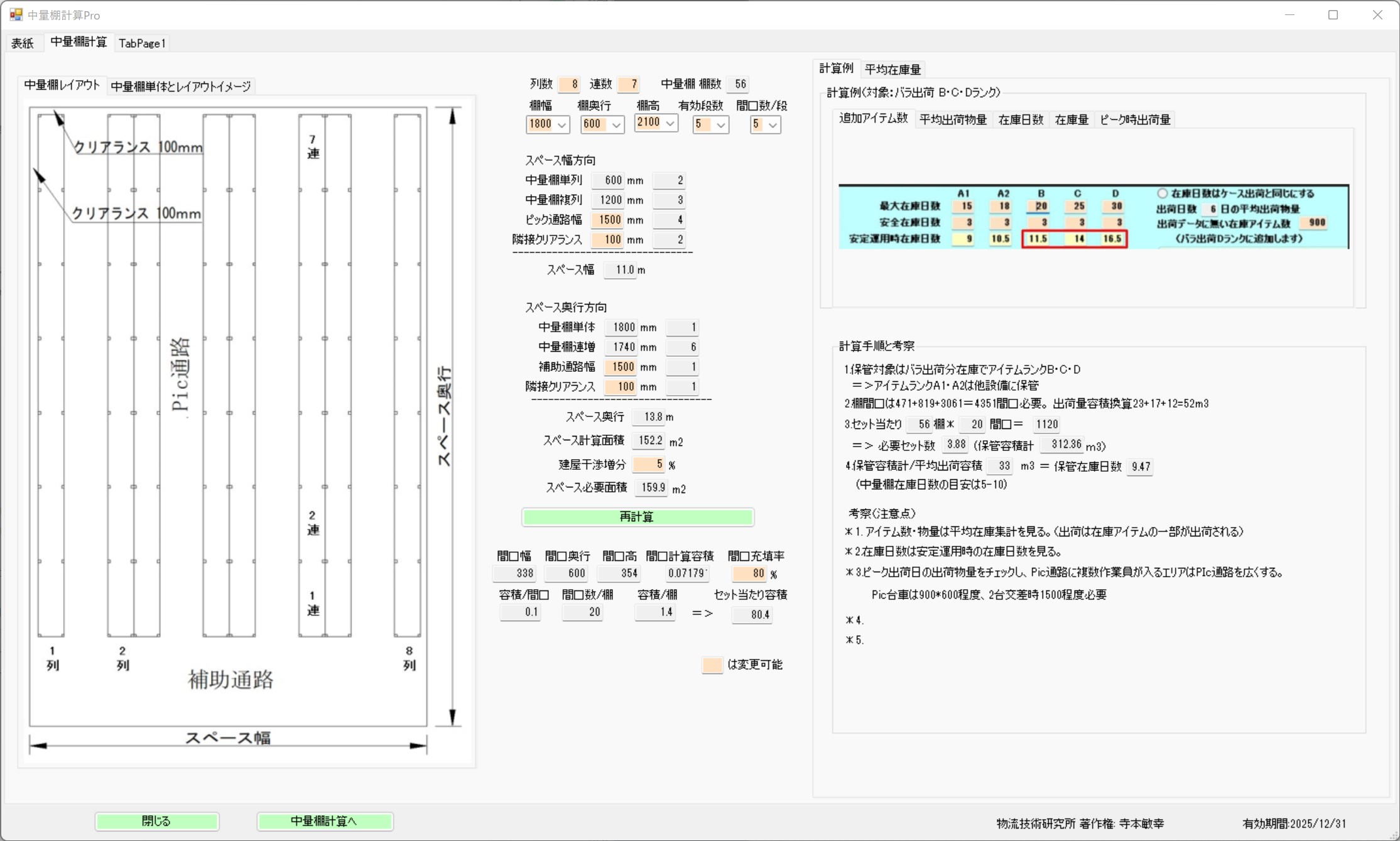
After setting the medium-duty rack specifications, number of rows, and number of bays, the installation area is calculated.
Rack Specifications, Number of Rows, and Number of Bays
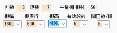
Rack Width: selectable from 1800, 2100, 2400
Rack Depth: selectable from 300, 450, 600, 900
Rack Height: selectable from 1800, 2100, 2400
Number of Tiers: selectable from 3, 4, 5, 6
Rack Slots: selectable from 2, 3, 4, 5, 6, 7, 8
Rack Slots
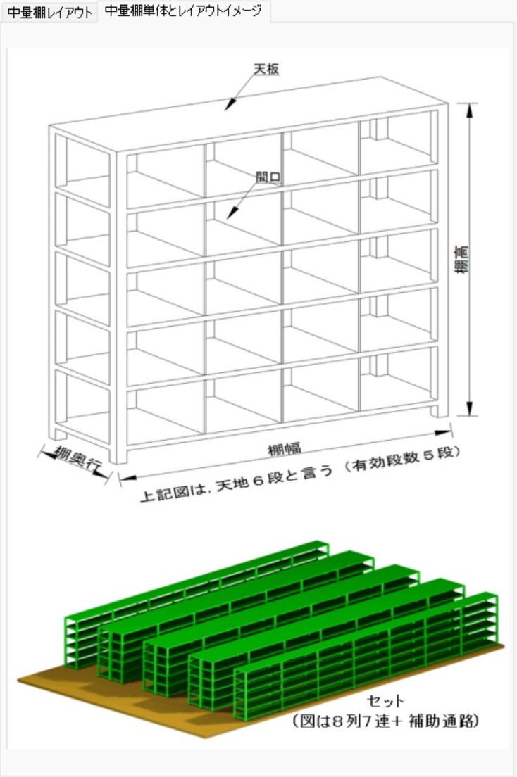
The number of stored items for medium-duty racks is determined by how many items are stored on one rack tier. Because the slots do not need to be equally spaced, combining small-volume items with large-volume items improves the rack fill rate.
Target items for storage are dispersed and managed in two locations: the inventory storage area and the shipping space area where medium-duty racks are installed.
When the target is 1000 items:
Center Inventory Days = 40 days, Center Inventory Volume = 100m3
Effective Medium-Duty Rack Storage Volume = 50m3, Rack Fill Rate = 70%
When Effective Medium-Duty Rack Storage Volume = 35m3
Medium-Duty Rack Inventory Days = (35m3 / 100m3) * 40 Days = 14 Days
The Inventory Storage Area is 26 days. The Shipping Operation Area is 14 days.
Considering the workload of replenishing from the inventory area to the shipping operation area, the shipping operation area (medium-duty racks) ideally should hold an inventory of 20 days or more.
Then, during the above calculation, what is the item count composition between the inventory storage area and the shipping operation area?
Number of items in the operation area is 1000 items
Number of items in the inventory storage area is 790 items
For the inventory storage area:
Number of Reduced Items = (Medium-duty rack inventory days / Center inventory days) * Number of items * 0.6
Number of Reduced Items = (14 / 20) * 1000 * 0.6 = 210
The above calculation is an example based on empirical values.
While automated warehouses and fixed PL rack heights exceed 3000mm and thus have an adjacent clearance of 200mm, the heights of flow racks and medium-duty racks are under 3000mm, so an adjacent clearance of 100mm is sufficient.
The total center inventory volume is obtained from the table below.
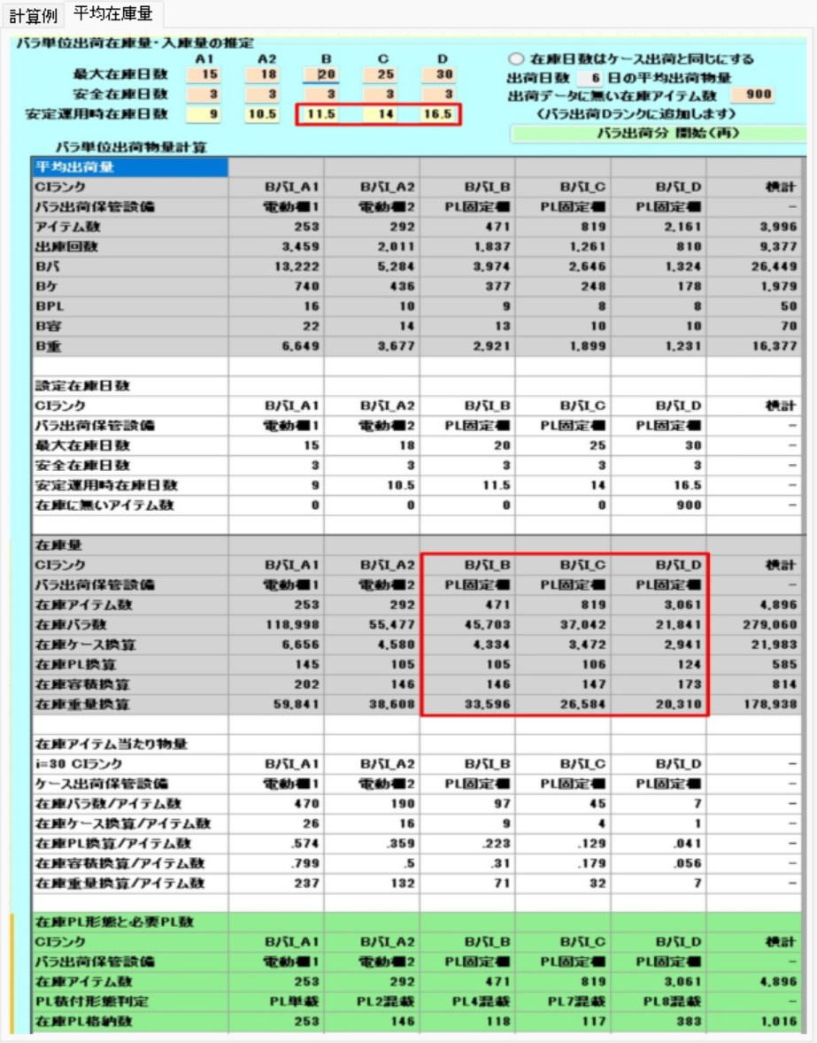
The table to the left is derived from inventory volume estimation calculations.
The target items for medium-duty racks are B_Piece_I_B, B_Piece_I_C, B_Piece_I_D.
For how to read the table, refer to the inventory volume estimation calculations.
Section 8: Sorting Machine Calculation
Basic Configuration and Dimension Calculation of Sorters
The overall dimensions of a sorting machine are broadly calculated as the sum of 3 sections: the "Infeed Section," the "Intermediate Section," and the "Drive Section."
- Calculation Formula for Overall Width:
$$ \text{Sorter Width} = \text{Front (Infeed Section)} + (\text{Intermediate Unit Length} \times \text{Number of Intermediate Chutes}) + \text{Rear (Drive Section)} $$
- Determining Factors for Chute Dimensions: The dimensions between chutes (sorting exits) and the length of the chutes themselves are determined based on the installation dimensions of the roll cages, etc., that receive the cargo.
⚙️ Layout Design and Space Management
After the dimensions of the sorter itself are finalized, verify interference with the building and other equipment, and calculate the incidental space necessary for operations.
- Consideration of Surrounding Space: It is necessary to consider the arrangements with the building and the margin space required for maintenance.
- Product Staging Space: Space for temporarily placing cargo waiting to be sorted is secured in addition to the calculated machine dimensions.
- Flexible Simulation: By changing the Tera Calculation setting values, you can immediately confirm how changes in the number of units or chute configuration affect the overall installation area.
Benefits of Introduction and Utilization
- Highly Accurate Layout Planning: Because it is a method that builds up the dimensions for each major component of the equipment, a design that accurately considers the positions of pillars and the distance from walls on-site is possible.
- Optimization of Logistics Flow: By grasping the physical length from the infeed section to the drive section, planning for connecting transport conveyors and worker placement can be streamlined.
Calculation Screen
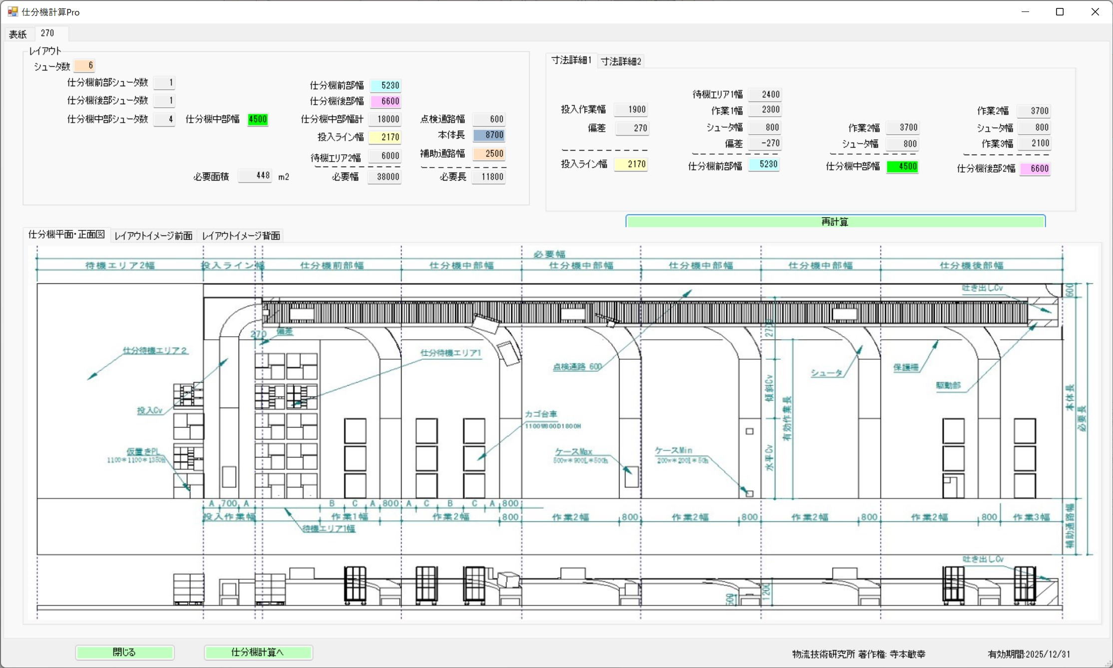
Photo Heading
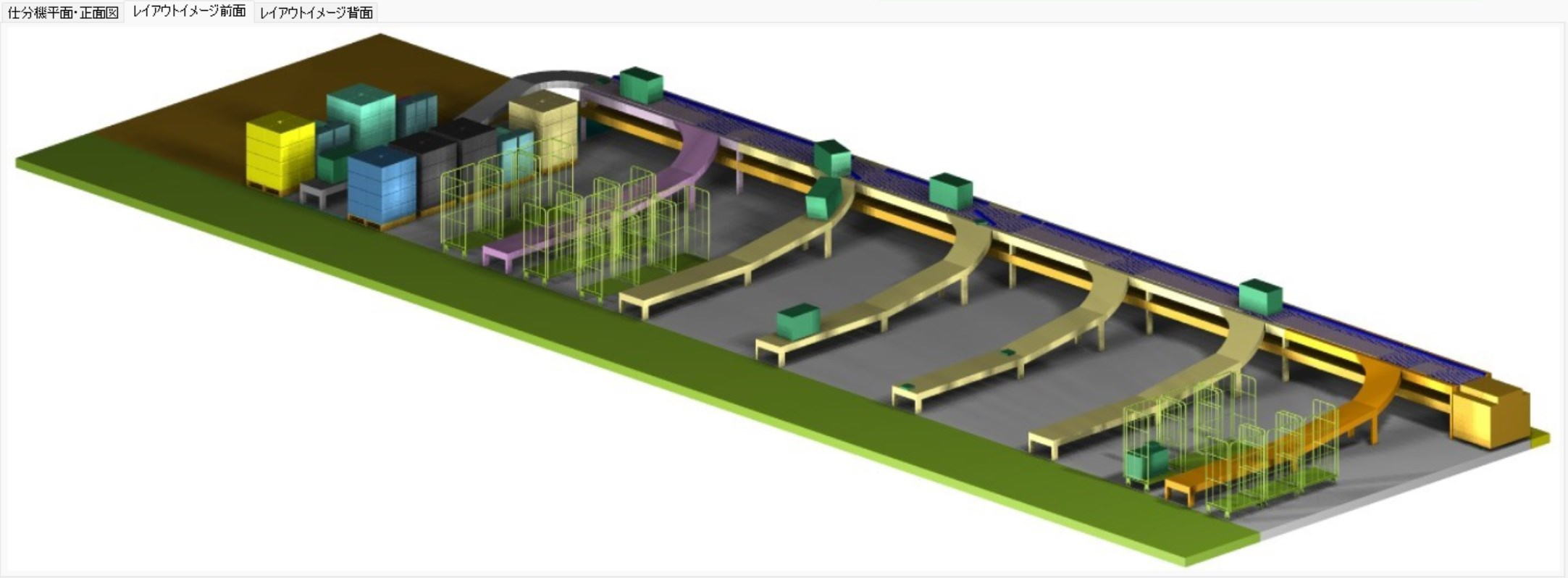
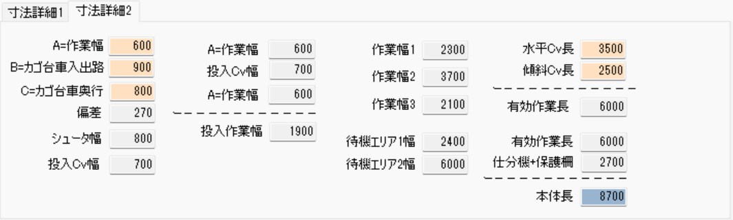
The sorting machine is divided into the infeed section (front), the intermediate section, and the drive section (rear) for calculation.
Sorter Width = Front + (Intermediate Section * Number of Intermediate Chutes) + Rear.
The dimensions between chutes and the length of the chutes are determined by the installation dimensions of the roll cages.
After confirming the dimensions of the sorter machine itself, calculate the product staging space by looking at the margin space and arrangements with the building and other equipment.
Please change the Tera Setting values and observe the changes in the installation area.
Section 9: Manual Sorting Calculation
Overview of Manual Sorting Calculation
Manual sorting is a common method performed in cases where dedicated automated equipment is not introduced, or in workplaces requiring effective use of space. The installation area fluctuates based on the following factors.
- Roll Cage Dimensions: The size of the roll cages to be used.
- Sorting Aisle Width: The space for workers and carts to pass through.
- Number of Destinations: The number of delivery destinations requiring sorting.
⚙️ Operational Characteristics and Targets
Manual sorting is flexibly performed by utilizing dead space or multi-purpose spaces within the distribution center.
- Location of Implementation: Infrequently used aisles or shipping staging spaces are often utilized.
- Target Cargo: The main targets are case shipments, primarily for in-house fleets or dedicated fleets.
- Difference from Courier Services: When using courier services, you simply affix shipping labels to the cases and transport them to the courier's designated area, so detailed sorting work on the center side is unnecessary.
Points for Efficiency
Operational ingenuity is effective for saving space and shortening work flow lines.
- Reduction of Staging Areas: If the worker who retrieved items from the inventory area transports and places them directly at the sorting destination, it eliminates the need to secure a temporary "sorting staging area."
- Flexible Area Simulation: By adjusting various numerical values on the Tera Calculation screen, you can instantly calculate the optimal required area corresponding to increases or decreases in volume.
Calculation Screen
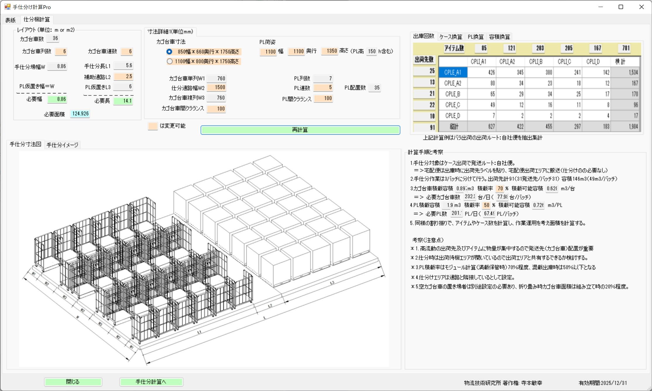
The installation area changes depending on the roll cage dimensions, sorting aisles, and the number of destinations.
Manual Sorting Image
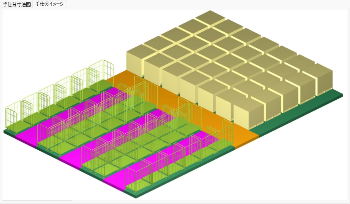
Manual sorting is often performed in infrequently used aisles or shipping staging spaces.
The target for sorting is case shipping, intended for in-house and dedicated fleets. Courier services do not require sorting as you simply affix shipping labels to the cases and transport them to the courier's area.
Also, if the worker who retrieved the goods from the inventory area performs the sorting directly, the necessity for a sorting staging area is eliminated.
Section 10: Inspection and Packing Calculation
Two Models for Inspection and Packing Calculation
The area is calculated using two approaches, depending on the strictness of the work and the degree of automation.
- Inspection & Packing Calculation 1 (100% Inspection Assumed): A standard work model where inspection and packing are performed for all shipped goods.
- Inspection & Packing Calculation 2 (Inspection-Less Assumed): Assumes a streamlined "inspection-less" flow, based on the Distribution Center Scale Calculation (Tera Calculation 2 Automatic).
⚙️ Item 1: Inspection & Packing Calculation 1 (Standard Model)
In this model, the required number of work sets and the area are derived based on the number of workers and processing capacity.
Work Configuration and Concept of Area Calculation
- Standard Structure: Assumes 1 set consists of a total of 5 people: 4 inspection workers and 1 assistant.
- Variable Factors: The required workspace increases or decreases depending on the dimensions of the roll cages used and the actual operational flow.
Calculation Simulation Example
A calculation example for inspecting 20,000 piece products per hour is as follows.
| Item | Numerical Value |
|---|---|
| Inspection Time per 1 Piece | 2 seconds |
| Capacity of 1 Set (4 people) | 7,200 pieces per hour ($3600 \text{ sec} / 0.5 \text{ sec}$) |
| Required Number of Sets | 3 Sets ($20,000 / 7,200 = 2.77 \dots$) |
| Total Required Area | 39 $m^2$ ($13 m^2 \times 3 \text{ Sets}$) |
Item 2: Inspection & Packing Calculation 2 (Inspection-Less Model)
This is a model that optimizes workspace and flow lines by simplifying or automating the inspection process.
- Automatic Linkage: Designed to link with the piece picking flowchart in Chapter 4, "Distribution Center Scale Calculation."
- Placement of Multiple Sets: When the processing volume is large, you can simulate the layout area when placing multiple work lines (sets).
Item 2: Inspection & Packing Calculation 2
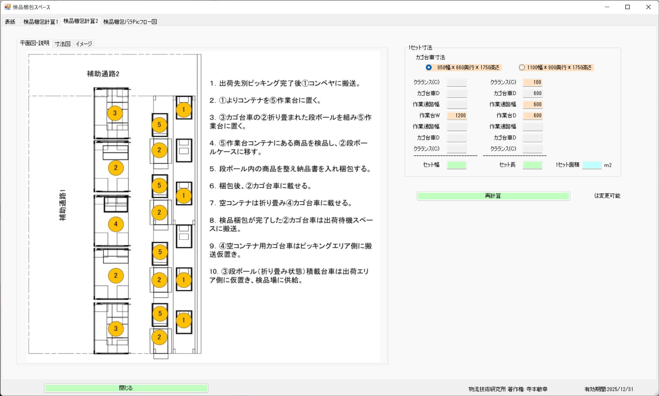
Inspection & Packing Calculation 2 Image
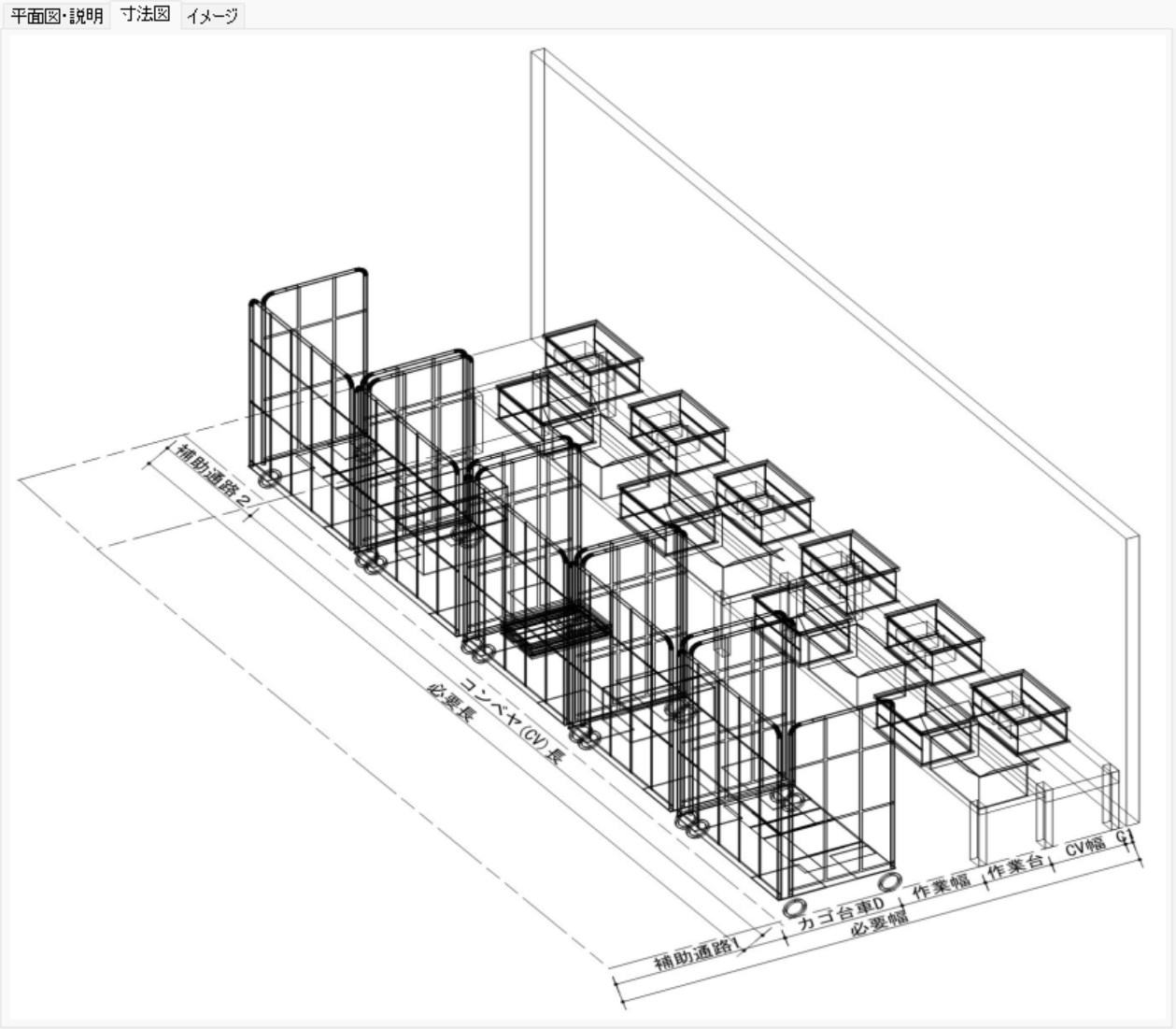
Photo Description
Inspection & Packing Calculation 1 assumes 100% inspection and packing
work, while Inspection & Packing Calculation 2 assumes the inspection-less
work adopted in Tera Calculation (Distribution Center Scale Calculation).
For inspection-less operations, refer to "Chapter 4, Tera Calculation 2 Automatic Distribution Center Scale Calculation, Item 7: Flowchart for Inspection/Packing Piece Pic".
Item 1: Inspection & Packing Calculation 1
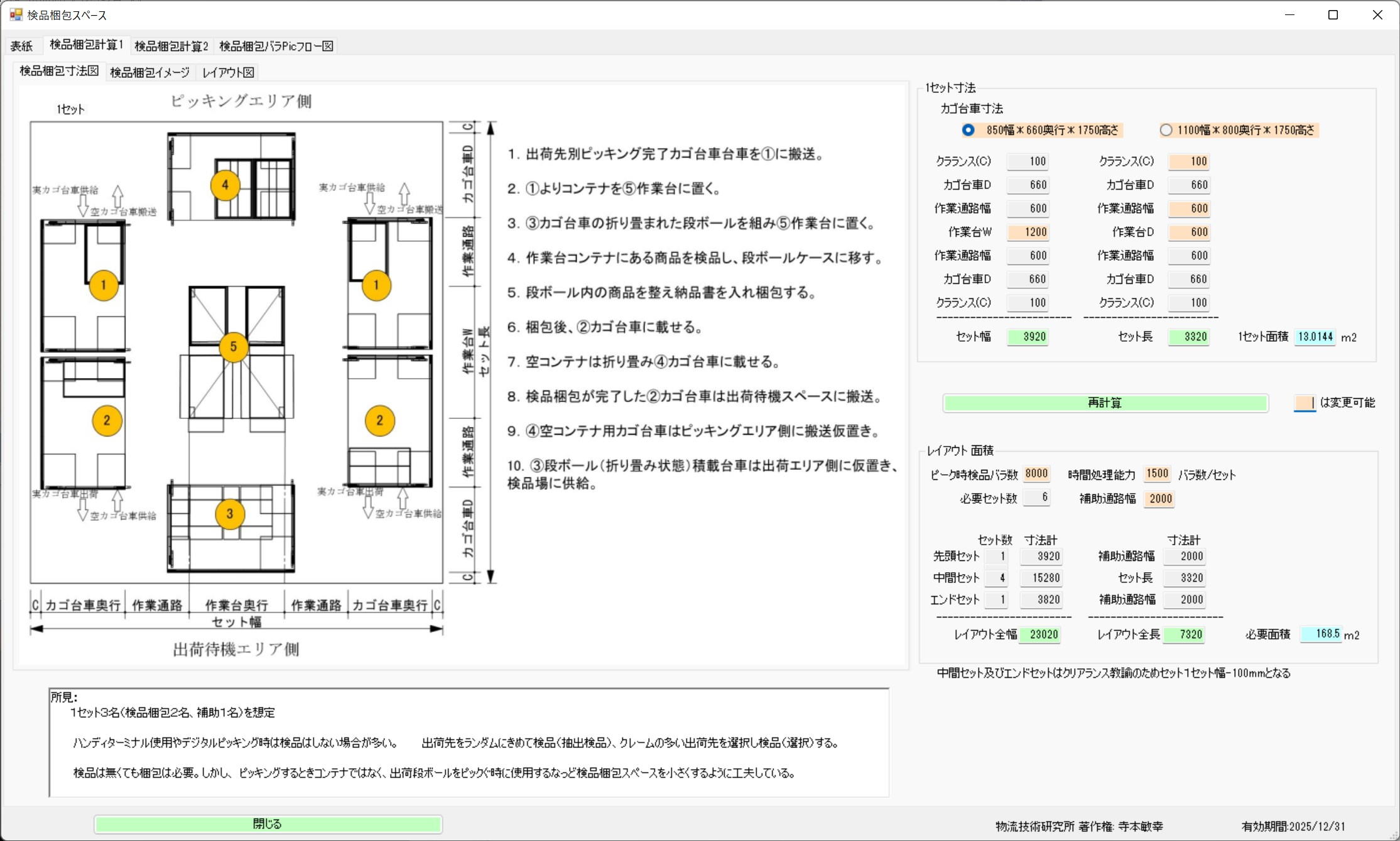
Photo Heading
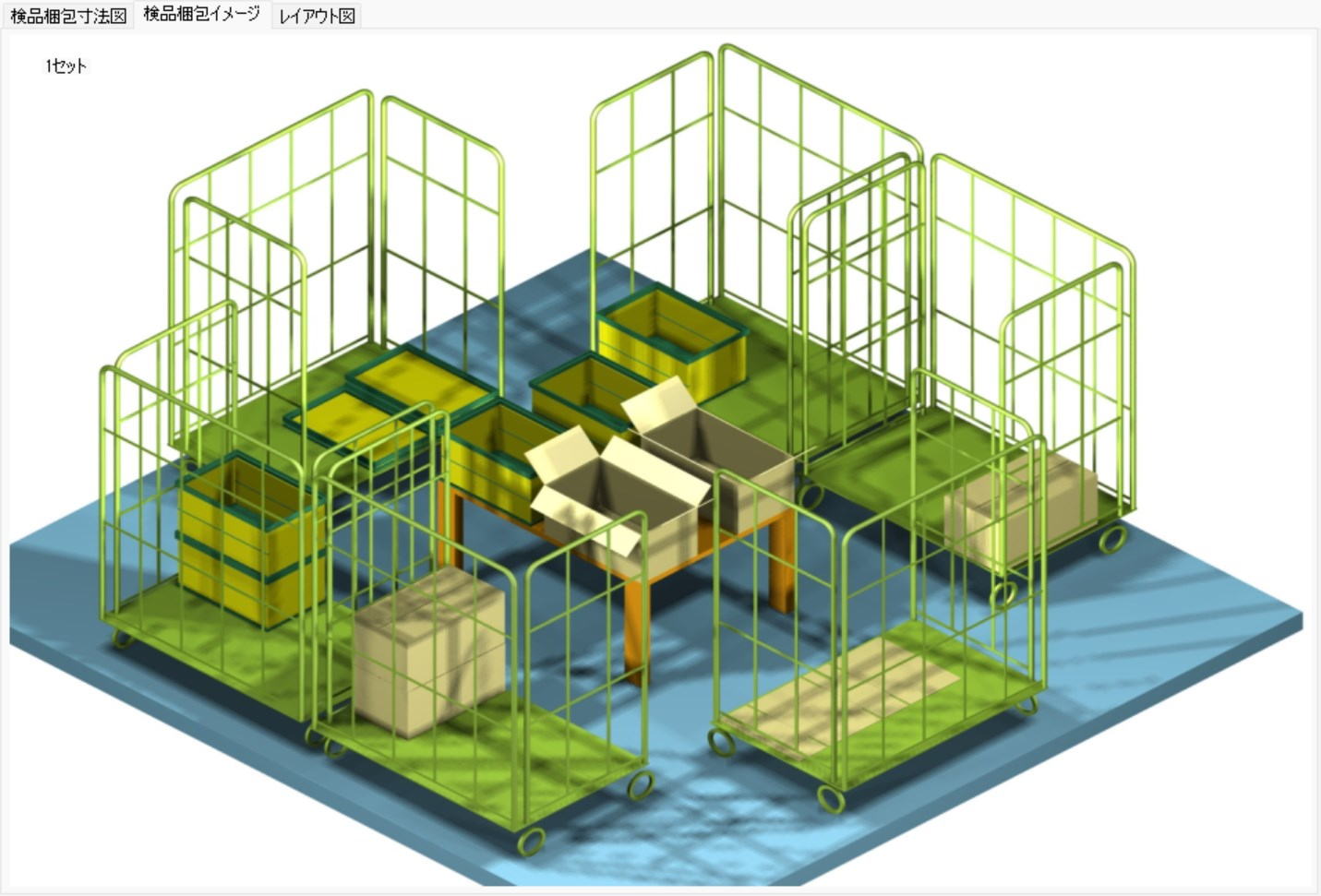
Assumes the work of 4 inspection workers and 1 assistant.
Workspace increases or decreases depending on roll cage dimensions and operation methods.
Calculation Example:
Inspecting 20,000 pieces per hour
Inspecting at 2 seconds per piece,
With 1 set of 4 people, it is possible to inspect at 0.5 seconds per piece,
The hourly processing capacity per set = 3600 / 0.5 = 7,200 pieces.
Required number of sets = 20000 / 7200 = 2.8 sets => 3 sets
The required area is 13m2 * 3 sets = 39m2.
Photo Heading
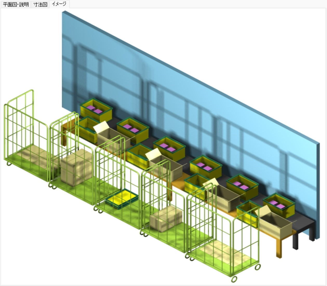
Photo description
Area Calculation for Multiple Sets
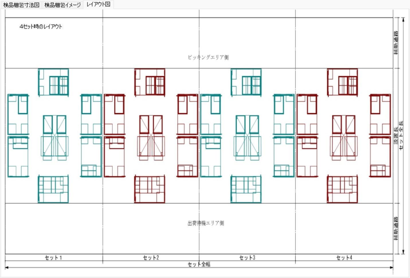
Photo description